OFDM has been around since the mid 1960s and is now used in a number of non-cellular wireless systems such as Digital Video Broadcast (DVB), Digital Audio Broadcast (DAB), Asymmetric Digital Subscriber Line (ADSL) and some of the 802.11 family of Wi-Fi standards. OFDM’s adoption into mobile wireless has been delayed for two main reasons. The first is the sheer processing power which is required to perform the necessary FFT operations. However, the continuing advance of signal processing technology means that this is no longer a reason to avoid OFDM, and it now forms the basis of the LTE downlink. The other reason OFDM has been avoided in mobile systems is the very high peak to average ratio (PAR) signals it creates due to the parallel transmission of many hundreds of closely-spaced subcarriers. For mobile devices this high PAR is problematic for both power amplifier design and battery consumption, and it is this concern which led 3GPP to develop the new SC-FDMA transmission scheme. Multiple access in the LTE downlink is achieved by using an elaboration of pure OFDM called orthogonal frequency division multiple access (OFDMA). This method allows subcarriers to be allocated to different users. This facilitates the trunking of many lower-rate users as well as enabling the use of frequency hopping to mitigate the effects of narrowband fading.
SC-FDMA
SC-FDMA is a hybrid transmission scheme which combines the low PAR characteristics of single-carrier transmission systems - such as those used for GSM and CDMA - with the long symbol time and flexible frequency allocation of OFDM. The principles behind SC The FDMA signal generation are shown in Figure 1.

 Figure 1. SC-FDMA signal generation
This is taken from Figure 1 of the study phase report for the LTE physical layer 3GPP TR 25.814. On the left hand side of Figure 1 the data symbols are depicted in the time domain. The symbols are converted to the frequency domain using an FFT, and then in the frequency domain they are mapped to the desired location in the overall carrier bandwidth. They must then be converted back to the time domain in order to have the cyclic prefix inserted prior to transmission. An alternative name for SC-FDMA is Discrete Fourier Transform Spread OFDM (DFT-SOFDM). An alternative description is provided in Figure 2 which shows, in frequency and time, how OFDMA and SC-FDMA would each transmit a sequence of 8 QPSK data symbols.
 Figure 2. Comparison of OFDMA and SC-FDMA transmitting a series of QPSK data symbols
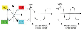
 Figure 3. Creating the time-domain waveform of an SC-FDMA symbol.
 Figure 2. Comparison of OFDMA and SC-FDMA transmitting a series of QPSK data symbols


No comments:
Post a Comment
Type your comment in here